Got questions? visit the
Toolbotics Community Forum
Need help using Tooli?
Visit the Tooli Help
Art2Gcode is used to convert vector artwork to Gcode for Toolbotics Tooli.
Want to laser engrave a halftone image? Learn how here.
About Art2Gcode
Art2Gcode allows you to open an SVG file and apply toolpaths to the paths that the SVG file contains. The toolpaths are used to create G-Code specifically for your Toolbotics Tooli machine - the code tells Tooli what to do when you run the job. The SVG may have been created in a vector drawing program such as Adobe Illustrator or Inkscape, or downloaded from a website. You can also do some basic drawing yourself within Art2GCode.
The tool box
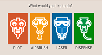
When you launch Art2GCode you will be greeted with the question 'What would you like to do?' This is to prompt you to choose what tool you will be using when you run this job on Tooli. Selecting the correct tool for the job is important so that the GCode that is created is correct for the tool that will be loaded in the machine.
So, if you are planning to laser cut some paper - choose Laser, if you are planning to airbrush a t-shirt choose Airbrush ... and so on. For the help examples we will be working with the Plot tool.
Quicklinks: click on the tool you learn how to create a tool path for:
Workspace
When you have chosen a tool you will enter the workspace for that tool. You can tell which workspace you are in by the colour theme and the graphic in the top left corner of the screen.
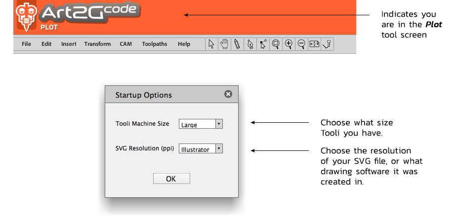
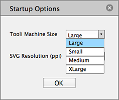 First you will be prompted to tell Art2Gcode what size Tooli machine you will be running your job on. The options are small, medium, large and extra large. Choose the appropriate size that matches your machine.
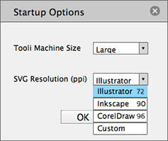
You will also need to input the resolution of the SVG you will be working with. This can be determined in a number of ways. If you SVG was created in Adobe Illustrator it will be 72ppi, if it was created in Inskcape it will be 90ppi, if it was created in CorelDraw it will be 96ppi. If your SVG was created in one of those programs then you can simply choose it from the menu. For advance users there is a custom setting where you can input a custom value.
Once you have specified these values click OK
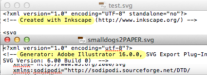
Not sure where your SVG originated? Locate the SVG on your computer - right click on it and open it in a text editor. In the header of the SVG it will indicate what software it was created in.
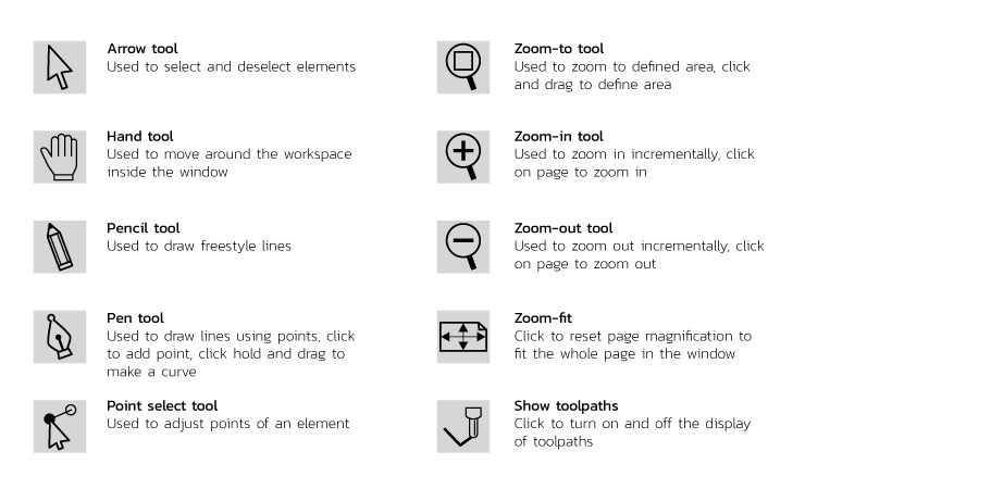
The Toolbar
Art2Gcode features a simple toolbar, Below is an explanation of each tool:
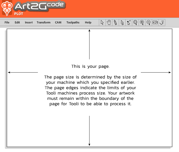
The Page
Open an SVG
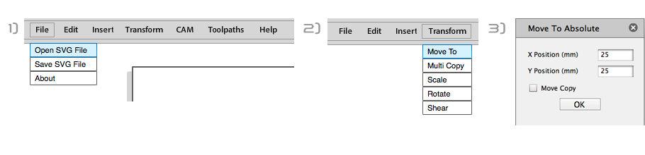
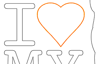
To open an SVG click File - Open SVG File. Browse to select the SVG file you require. Click Open. The artwork will appear on the page with the lines highlighted in red. The red highlight means the artwork is currently selected.
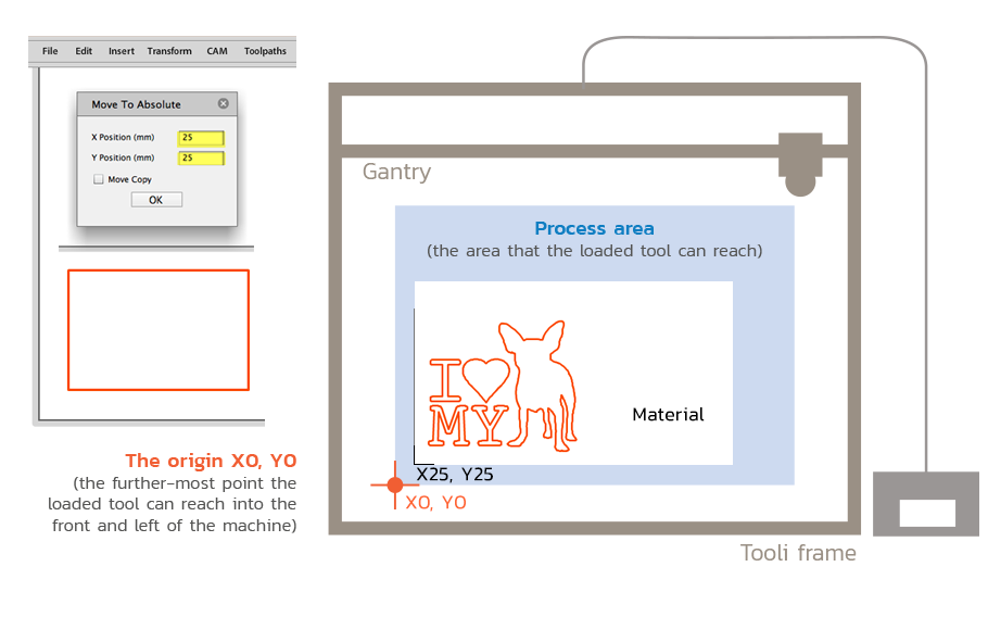
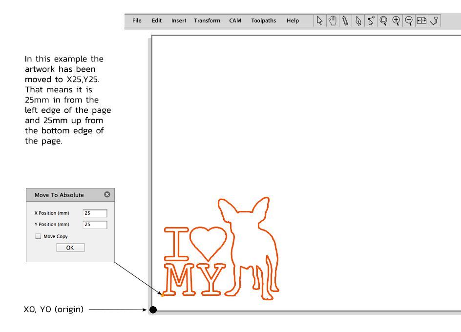
Position the artwork on the page
To position the artwork on the page - let's say we want it in the bottom left hand corner... click Transform - Move to - and enter the coordinates for where you want the bottom left of the SVG bounds to be positioned. Click OK.
Selecting and deselecting artwork
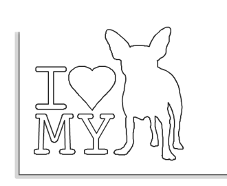
Click anywhere on the page to deselect, when the artwork is not selected it will display with a black line.
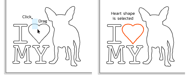
To select artwork click and drag so that you select part of the line that you want to select.
You can also click on the line but it requires more accuracy, we find it easier to use the 'click-drag' technique.
Find out more about creating, transforming and copying elements on the page...
Specifying a toolpath
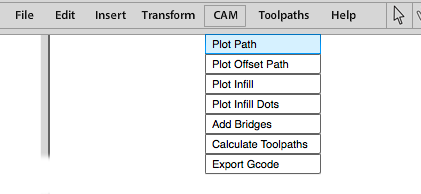 To apply a toolpath to the line, with the line selected (highlight in red) go CAM - Plot on path.
Find out more about making toolpaths for different tools...
This dialogue box will appear:
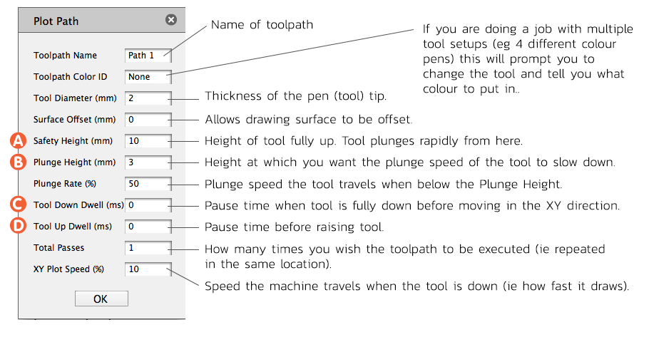
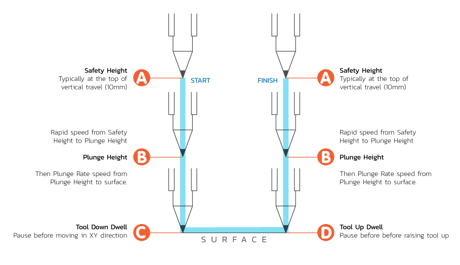
Below is a diagram to help visualise how each of these settings will determine the Z-axis movement of the machine.
once you have put in your settings click OK and you will see the selected line now highlighted in yellow.
Calculate toolpath
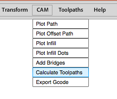
With the line still selected go CAM - Cacluate toolpaths.
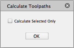
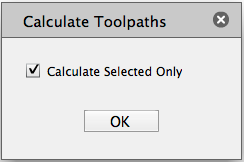
If you wish to only make a Toolpath for the selected line check Calculate Selected Only. Click OK.
Note: if you leave Calculate Selected Only unchecked all the toolpaths in the document will be calculated.
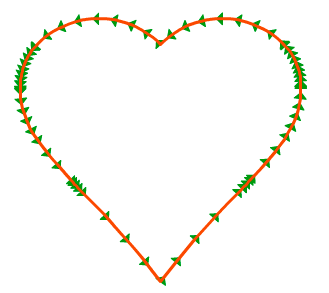
The toolpath has now been created - indicated with green arrows showing the direction of the path, the red line indicating the line is still selected.
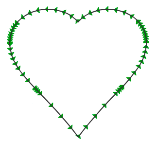
Click anywhere on the page to deselect the path.
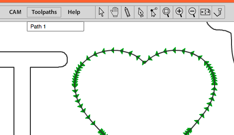
Now if you click Toolpaths in the menu bar you can see the toolpath is there - named Path 1.
You can now carry on and create other toolpaths in the same document. As they are created they will be added to the list.
Exporting GCode
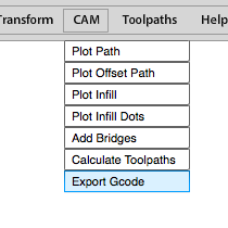
Click CAM - Export Gcode.
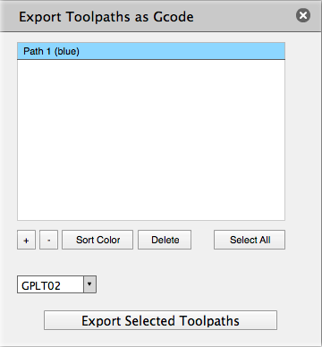
In this dialogue box you can select and change the order of the toolpaths, sort them by colour alphabetically, or select and move them up and down the list.
The Gcode will be created in the order the toolpaths are sort - from top to bottom. Only toolpaths that are selected (highlighted in blue) will be exported.
Once you have sorted the toolpath into the order you want the machine to execute them. Click Export Selected Toolpaths.
You will be prompted to save the .gplt file to a location on your computer.
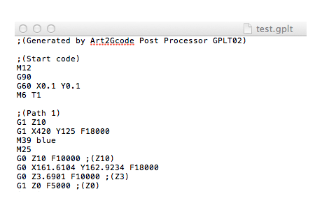
Now (just for fun) browse your computer and open the file with a text editor and it should look something like this. This is the code that controls Tooli (now close the file).
Copy this file to your SD card and then you can insert it into Tooli's control box and load the job.
Where to put the material?
When positioning the artwork on the page in Art2Gcode using the Transform - Move to command the X and Y coordinates you input will be the further-most front left point of the job output). Here is an example: